Computer Vision for German Automotive Surface Defect Detection: Technologies, Applications, and How to Choose

Author
Ravi Prajapati
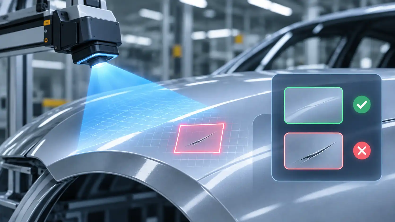
Explore computer vision for automotive surface defect detection in Germany. Compare AI, cameras, lighting, false rejects and production integration.
Automotive manufacturers in Germany need to identify surface defects before vehicles and components reach the next production stage. Scratches, dents, paint irregularities, coating defects, and surface contamination can affect product quality, customer satisfaction, and manufacturing costs.
Computer vision systems use industrial cameras, controlled lighting, image-processing algorithms, and AI models to inspect automotive surfaces automatically. These systems can support inline inspection of painted body panels, metal components, wheels, cast parts, and other automotive products.
However, automotive surface defect detection is not simply a matter of installing a camera and training an AI model. Reflective materials, curved surfaces, changing illumination, small defects, production-line movement, and limited defect samples can make inspection difficult.
For manufacturers in Germany, selecting the right solution requires evaluating the inspection method, lighting arrangement, camera setup, defect classification approach, production-line integration, and the cost of false decisions.
This guide explains the technologies used in automotive surface defect detection, compares the available inspection methods, reviews relevant research and solution providers, and outlines how manufacturers can evaluate a computer vision system for production use.
What Is Computer Vision for Automotive Surface Defect Detection?
Computer vision for automotive surface defect detection is an automated inspection technology that analyzes images of vehicle surfaces or automotive components to identify, classify, and locate visible defects.
A typical system combines:
Industrial cameras
Specialized lighting
Image acquisition hardware
Image-processing software
Machine learning or deep learning models
Inspection and classification logic
Production-line integration
The system captures images of a component, processes the visual information, and determines whether the inspected surface meets the defined quality requirements.
Depending on the application, the system may classify defects, mark their locations, estimate defect dimensions, or flag the component for further inspection.
How the Inspection System Works
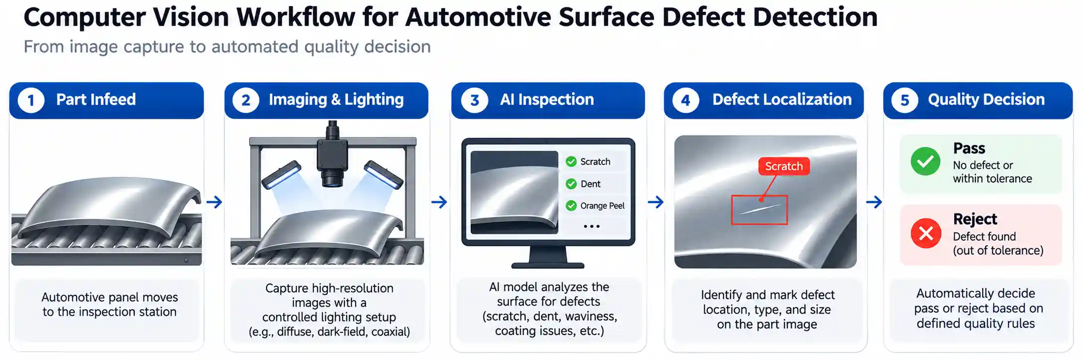
A standard computer vision inspection workflow follows these steps:
Component positioning: The automotive part moves into the inspection area or is positioned at a defined station.
Image acquisition: Industrial cameras capture the surface under controlled lighting.
Image preprocessing: The system corrects image inconsistencies and prepares the image for analysis.
Defect detection: Computer vision algorithms identify potential scratches, dents, coating defects, or other irregularities.
Defect classification: The system determines the defect type and its severity, where the model has been trained to do so.
Quality decision: The component is marked as accepted, rejected, or requiring human review.
Data recording: Inspection results can be sent to production, quality management, or traceability systems.
Why Automotive Surface Inspection Matters in German Manufacturing
Germany has a significant automotive manufacturing ecosystem involving vehicle manufacturers, Tier 1 suppliers, Tier 2 suppliers, component manufacturers, and specialized production facilities.
Surface inspection is relevant across multiple production stages, including:
Body-in-white manufacturing
Automotive painting and finishing
Metal stamping
Die casting
Wheel and hub manufacturing
Interior and exterior component production
Final vehicle quality inspection
Manual inspection remains useful, particularly for subjective visual quality assessment and unusual defects. However, manual inspection can be affected by operator fatigue, differences in experience, inspection speed, and inconsistent viewing conditions.
Computer vision can support inspection by applying repeatable image capture and defined detection logic. It can also create inspection records that help quality teams analyze defect patterns.
The value of automation depends on the application. A system that detects scratches on a painted body panel may require a different camera and lighting arrangement from a system that inspects a cast aluminium component.
Common Automotive Surface Defects Detected by Computer Vision
The defect type, material, surface finish, and inspection objective influence the choice of technology.
Defect Type | Description | Common Automotive Applications | Suitable Inspection Approach |
|---|---|---|---|
Scratches | Linear marks or damage on a surface | Painted panels, metal trim, glass | Dark-field lighting, image processing, AI |
Dents | Local deformation or depression | Body panels, sheet metal, cast components | Structured light, deflectometry, 3D vision |
Paint defects | Irregularities in paint application or finish | Vehicle body panels, bumpers | Diffuse lighting, dome lighting, AI segmentation |
Orange peel | Textured appearance caused by paint surface variation | Painted vehicle body surfaces | Diffuse illumination, specialized surface analysis |
Contamination | Dust, particles, or foreign material | Paint shops, coated components | Coaxial or diffuse illumination, AI classification |
Coating irregularities | Uneven coating or localized surface variation | Metal parts, painted components | Controlled lighting, image processing |
Scuffs | Surface abrasion or rubbing marks | Interior and exterior components | Dark-field illumination, AI |
Pits and pores | Small holes or surface imperfections | Cast metal parts, machined components | High-resolution imaging, segmentation |
Edge defects | Damage or irregularity around component boundaries | Stamped and machined parts | Low-angle lighting, edge detection |
Reflective surface anomalies | Changes in reflected patterns or geometry | Glossy painted panels, polished metal | Deflectometry, structured light |
Important: Not every defect can be reliably detected using a single camera, lighting arrangement, or AI model. Some defects require multiple inspection techniques.
Technologies Used for Automotive Surface Defect Detection
1. Industrial Cameras
Industrial cameras capture the images used by the inspection system. Camera selection depends on the inspection speed, field of view, defect size, surface geometry, and available installation space.
Area-Scan Cameras
Area-scan cameras capture a complete two-dimensional image in a single exposure.
They are suitable for:
Stationary components
Robot-assisted inspection
Individual component inspection
Flexible inspection stations
Parts that can be positioned within a defined field of view
Line-Scan Cameras
Line-scan cameras capture one line of pixels at a time. The system builds a complete image as the component or camera moves.
They are suitable for:
Continuous production lines
Large surfaces
Moving automotive components
High-speed inspection
Long or wide inspection areas
Multi-Camera Systems
Multi-camera systems use multiple cameras to inspect different sides, angles, or regions of a component.
They can help with:
Complex component geometry
Large inspection areas
Multiple viewing angles
Reduced blind spots
Simultaneous inspection of different surfaces
Camera Type | Best Suited For | Advantages | Limitations |
|---|---|---|---|
Area-scan | Stationary or indexed inspection | Simple image capture, flexible positioning | May require multiple images for large parts |
Line-scan | Continuous moving surfaces | High-resolution inspection over long surfaces | Requires synchronized movement and acquisition |
Multi-camera | Complex or multi-sided components | Wider coverage, multiple viewing angles | Higher system complexity and calibration effort |
2. Camera Resolution and Defect Size
Camera resolution is one of the factors that influences whether a defect can be detected.
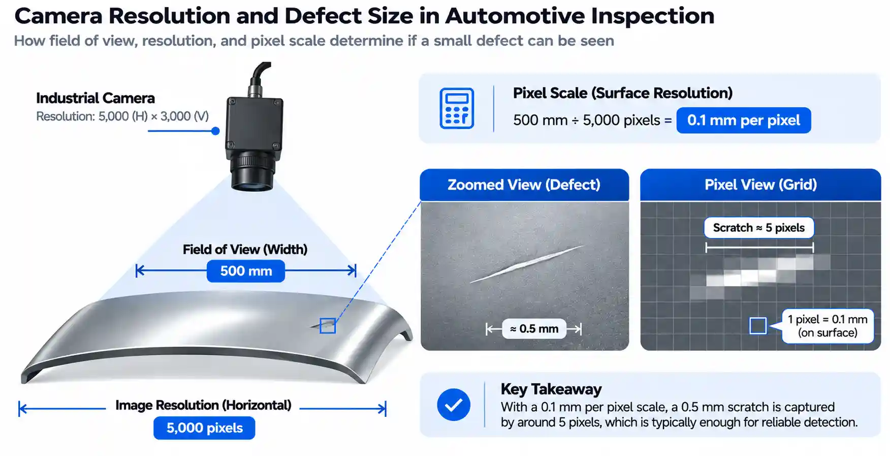
A useful initial calculation is:

For example:
Inspection field of view: 500 mm
Camera resolution across the field: 5,000 pixels

This means that each pixel represents approximately 0.1 mm of the inspected surface in that direction.
A scratch measuring 0.5 mm across would span approximately five pixels under these assumptions.
However, this calculation is only a starting point. Pixel resolution alone does not guarantee defect detection. Actual performance also depends on contrast, optics, illumination, focus, sensor quality, motion blur, surface reflectivity, and the model’s detection capability.
3. Lighting Techniques for Automotive Surface Inspection
Lighting is one of the most important parts of an automotive surface defect detection system.
Automotive components can have glossy, reflective, curved, textured, or coated surfaces. A defect that is visible under one lighting arrangement may be difficult to identify under another.
The lighting method should be selected according to the defect type and the surface characteristics.
Diffuse Lighting
Diffuse lighting spreads light evenly across the inspected surface.
Best for:
General surface inspection
Reducing harsh shadows
Broad surface variation
Painted panels
Dark-Field Lighting
Dark-field lighting directs light at a low angle across the surface.
Best for:
Fine scratches
Scuffs
Shallow surface irregularities
Edge defects
Coaxial Lighting
Coaxial lighting directs illumination along the camera’s viewing axis, often using a beam splitter.
Best for:
Flat reflective surfaces
Certain print marks
Surface contamination
Coating irregularities
Dome Lighting
Dome lighting creates diffuse illumination from multiple directions around the inspection area.
Best for:
Curved surfaces
Glossy components
Reducing strong reflections
Texture and surface finish inspection
Structured-Light Inspection
Structured-light systems project known patterns onto a surface and analyze how those patterns change.
Best for:
Surface geometry
Dents
Deformations
Shape variation
Deflectometry
Deflectometry analyzes reflected patterns from highly reflective surfaces. It is particularly useful when the surface itself behaves like a mirror.
Best for:
Glossy painted body panels
Reflective curved components
Surface waviness
Geometric deformation
Lighting Comparison Table
Lighting Technique | Primary Strength | Suitable Defects | Common Surface Type |
|---|---|---|---|
Diffuse | Uniform illumination | Broad surface variation, scratches, dents | Painted and textured |
Dark-field | Highlights small surface irregularities | Micro-scratches, scuffs, edge defects | Metal and coated surfaces |
Coaxial | Controlled reflection along the camera axis | Print marks, contamination, coating defects | Flat reflective surfaces |
Dome | Diffuse light from multiple directions | Texture variation, orange peel, unevenness | Curved or glossy surfaces |
Structured light | Surface geometry measurement | Dents, deformation, shape variation | 3D automotive components |
Deflectometry | Measures reflected pattern distortion | Surface waviness, geometric anomalies | Highly reflective surfaces |
Computer Vision and AI Methods for Defect Detection
Different computer vision approaches solve different inspection problems. Manufacturers should select a method based on defect visibility, available data, required precision, and production conditions.
1. Traditional Image Processing
Traditional image processing uses defined rules to analyze images.
Typical methods include:
Thresholding
Edge detection
Contour analysis
Morphological operations
Template matching
Texture analysis
Image filtering
Advantages
Relatively easy to interpret
Can work well for stable, clearly defined defects
May require less training data
Can be computationally efficient
Limitations
Sensitive to changes in lighting and surface appearance
Requires manual tuning
May struggle with complex defect variation
Traditional image processing is often suitable when the surface, lighting, and defect characteristics remain consistent.
2. Deep Learning-Based Defect Detection
Deep learning models learn visual patterns from training images.
They can be used to:
Detect defects
Classify defect types
Locate defects
Segment defect regions
Identify abnormal surface patterns
Deep learning can be useful when defects vary in shape, size, texture, or appearance.
However, the model's performance depends on the quality and representativeness of its training and validation data.
3. Object Detection
Object detection identifies defects and provides bounding boxes around them.
This method is useful when the inspection system needs to identify:
The presence of a defect
Its approximate location
Its defect category
The number of defects
Object detection is often suitable for defects that are visually distinguishable and do not require precise pixel-level boundaries.
4. Semantic Segmentation
Semantic segmentation classifies individual pixels in an image.
For automotive inspection, segmentation can help determine the exact region occupied by a scratch, paint defect, or surface irregularity.
It can support:
Defect area measurement
Defect shape analysis
More precise localization
Severity estimation based on defined criteria
Segmentation can require more detailed annotations than object detection, making the data preparation process more demanding.
5. Anomaly Detection
Anomaly detection is useful when defective samples are limited or when manufacturers need to identify previously unseen surface irregularities.
A typical approach learns the appearance of acceptable products and flags deviations from that appearance.
This can be useful for:
New defect types
Rare defects
Limited defect datasets
Changing manufacturing conditions
An anomaly detection system does not automatically determine whether every unusual pattern is a real quality defect. Its outputs still need validation against the manufacturer's quality criteria.
6. 3D Computer Vision
3D computer vision captures or estimates the geometry of a surface.
It can help inspect:
Dents
Deformations
Surface waviness
Geometric deviations
Shape inconsistencies
3D methods can complement 2D image analysis when a defect is difficult to distinguish from changes in surface color or reflection.
AI Method Comparison
Method | Primary Use | Strengths | Limitations |
|---|---|---|---|
Traditional image processing | Defined, repeatable defects | Interpretable, efficient | Requires rule tuning |
Object detection | Defect localization and classification | Fast, practical for visible defects | Bounding boxes may be imprecise |
Segmentation | Pixel-level defect boundaries | Detailed localization | Annotation-intensive |
Anomaly detection | Unknown or rare defects | Can use mostly normal samples | May flag harmless variations |
3D vision | Geometry and deformation inspection | Measures surface shape | Higher equipment and calibration complexity |
Multi-modal vision | Combined visual and geometric inspection | Can provide complementary evidence | More complex integration |
Recent Research in Automotive Surface Defect Detection
Research into automotive inspection is addressing several persistent challenges: reflective surfaces, limited defect data, complex component geometry, and the need for reliable inline detection.
The following examples are research findings or reported studies. Their results should be interpreted within the specific experimental conditions of each paper.
Dual-Modality Imaging for Automotive Paint Surfaces
A 2026 study published in Measurement investigated automotive paint surface inspection using modulation intensity decoding and phase-measuring deflectometry.
The research combines complementary imaging information to reveal fine defect textures and geometric deformation on reflective, curved paint surfaces.
This highlights an important principle: using complementary imaging methods may provide more information than relying on a single conventional camera image.
Synthetic Data for Automotive Surface Defect Segmentation
A 2026 Springer study explored physics-inspired synthetic data for automotive surface defect segmentation.
One challenge in industrial inspection is the limited availability of real defect images with accurate pixel-level annotations. Synthetic data can help expand training datasets, although it must be validated against real production images.
Wheel Hub Defect Detection
A 2026 study on wheel hub defect detection described a specialized model and a multi-camera binocular vision arrangement.
This illustrates how inspection architectures can be designed around the geometry and defect patterns of a particular component instead of applying one generic model to all automotive surfaces.
Inline Inspection of Die-Cast Components
A 2024 Procedia CIRP study examined inline deep learning inspection of a die-cast hybrid vehicle component. The study reported a 98% true positive rate under its experimental conditions.
This figure should not be treated as a universal performance benchmark for automotive defect detection systems. Performance depends on the component, defect distribution, data, imaging conditions, and evaluation setup.
Anomaly Detection for Underbody Sealant Inspection
Research in 2026 explored anomaly detection and localization for car underbody sealant quality inspection.
The work highlights challenges such as complex geometry, lighting variation, and image noise. These are relevant considerations for automotive inspection systems operating in production environments.
Automotive Computer Vision Solution Providers
Manufacturers evaluating automotive surface inspection systems may consider established industrial vision software, camera suppliers, and specialized inspection solution providers.
The companies below are examples of providers with publicly documented machine vision or automotive inspection offerings. This is not a ranked list.
1. ZEISS
ZEISS provides automotive body and surface inspection technologies, including automated systems for geometry and surface defect inspection.
Its ABIS inspection solutions are associated with automated body surface inspection and real-time quality assessment.
automated
2. ISRA VISION
ISRA VISION provides industrial inspection solutions, including CarPaintVision for detecting and classifying relevant paint defects on vehicle body surfaces.
3. MVTec HALCON
MVTec HALCON is an industrial machine vision software platform used for image processing and inspection applications. It supports conventional machine vision and deep learning approaches.
4. Basler
Basler supplies industrial cameras and machine vision components used in inspection applications. Its automotive machine vision resources include camera and system solutions for surface and clearance inspection.
5. Cognex
Cognex provides machine vision systems and software for industrial inspection, identification, and quality control.
Solution Provider Comparison
Provider | General Area | Potential Evaluation Focus |
|---|---|---|
ZEISS | Automotive body and surface inspection | Automated geometry and surface quality inspection |
ISRA VISION | Automotive paint inspection | Paint defect detection and classification |
MVTec HALCON | Machine vision software | Custom image-processing and deep learning applications |
Basler | Industrial cameras and vision components | Camera selection, imaging setup, system design |
Cognex | Industrial machine vision | Inspection, defect detection, and production applications |
Selection note: A supplier’s product documentation establishes its stated capabilities, not its performance on a particular manufacturing line. Manufacturers should validate the system using their own components and defect samples.
False Rejects, False Accepts, and Inspection Costs
A computer vision system must do more than detect defects. It must make decisions that align with the manufacturer's quality requirements.
Two important inspection errors are:
False reject: An acceptable component is incorrectly classified as defective.
False accept: A defective component is incorrectly classified as acceptable.
Both can create operational costs.
Inspection Outcome | Actual Component Condition | System Decision | Result |
|---|---|---|---|
True positive | Defective | Reject | Correct detection |
True negative | Acceptable | Accept | Correct decision |
False positive / false reject | Acceptable | Reject | Unnecessary rejection |
False negative / false accept | Defective | Accept | Defect escapes inspection |
How False Rejects Affect Manufacturing Costs
False rejects can lead to:
Unnecessary rework
Additional manual inspection
Material waste
Production delays
Increased quality assurance costs
Illustrative Cost Example
Assume a manufacturing facility inspects one million components annually.
If 2% of acceptable components are incorrectly rejected, and the average cost associated with each false reject is €8:

Illustrative scenario only. The values are assumptions, not an industry benchmark.
The example shows why manufacturers should evaluate the economic impact of inspection errors, rather than focusing exclusively on model accuracy.
How to Reduce False Rejects
Manufacturers can reduce unnecessary rejections by:
Improving lighting consistency.
Using representative images of acceptable surface variation.
Training models with diverse production samples.
Defining defect severity thresholds.
Separating harmless cosmetic variation from genuine defects.
Using a human review process for uncertain cases.
Monitoring performance after deployment.
Evaluating false reject and false accept rates separately.
Which Metrics Should Be Evaluated?
Metric | What It Measures | Why It Matters |
|---|---|---|
Precision | How many detected defects are actual defects | Helps control false alarms |
Recall | How many actual defects are detected | Helps reduce missed defects |
False reject rate | Acceptable items incorrectly rejected | Measures unnecessary rejection |
False accept rate | Defective items incorrectly accepted | Measures quality escape risk |
F1 score | Balance between precision and recall | Useful for model comparison |
Defect localization accuracy | How well the defect region is identified | Important for segmentation and severity |
Inspection cycle time | Time required to inspect a component | Determines production-line suitability |
A system with high recall but poor precision may detect most defects while rejecting too many acceptable parts. A system with high precision but poor recall may miss defects.
The appropriate balance depends on the defect severity, customer requirements, and production process.
Production-Line Integration for Automotive Inspection
Computer vision inspection systems need to communicate with manufacturing equipment and quality systems.
A production-ready architecture may include:
Industrial cameras
Lighting controllers
Image acquisition hardware
Edge computing hardware
Vision inspection software
PLCs
MES
QMS
Industrial communication interfaces
Typical Integration Workflow
A PLC triggers image acquisition when a component reaches the inspection position.
The camera captures the component surface.
The inspection software analyzes the images.
The system returns the inspection result.
The PLC uses the result for production control.
Inspection information is stored in a manufacturing or quality system.
Quality teams analyze defect trends and production patterns.
PLC Integration
PLCs coordinate machine operations and production processes.
The vision system may communicate inspection results such as:
Accept
Reject
Defect detected
Inspection complete
Inspection failed
Review required
The communication method depends on the existing plant architecture.
MES Integration
Manufacturing Execution Systems can help connect inspection results with production records.
Possible data includes:
Component identification
Production order
Inspection timestamp
Defect category
Inspection result
Machine or station information
QMS Integration
Quality Management Systems can support:
Defect tracking
Quality records
Non-conformance management
Corrective action workflows
Quality trend analysis
OPC UA and Industrial Communication
OPC UA can support interoperability between machine vision systems and manufacturing equipment.
It may be used to exchange information with PLCs, line controllers, MES, SCADA, or ERP systems, depending on the implementation.
Important: The inspection system must be validated not only for image analysis but also for trigger timing, communication reliability, cycle time, and correct handling of system failures.
Standards and Quality Considerations in Germany
Automotive manufacturers and suppliers may need to align their quality processes with industry standards and customer-specific requirements.
Relevant standards and frameworks can include:
Standard / Framework | General Relevance |
|---|---|
IATF 16949 | Quality management requirements for automotive production and relevant service parts organizations |
VDA 6.3 | Process audit framework used in the automotive industry |
VDA 5 | Measurement and inspection process capability considerations |
ISO 9001 | General quality management system requirements |
VDA 6.3:2023 is the relevant edition referenced in the cited material.
A computer vision system does not automatically become certified or compliant simply because it is used in a certified manufacturing environment.
The manufacturer must assess how the inspection process fits its own quality system, measurement requirements, customer specifications, and validation procedures.
How to Choose a Computer Vision System for Automotive Surface Defect Detection
Choosing a system requires a structured evaluation. The best solution depends on the component, defect types, production environment, and required inspection performance.
Step 1: Define the Inspection Objective
Start by identifying what the system needs to inspect.
Examples:
Scratches on painted body panels
Dents on metal components
Paint defects on vehicle bodies
Surface pores on die-cast parts
Defects on automotive wheels
Surface waviness on reflective components
Do not begin with the AI model. Begin with the quality problem.
Step 2: Define the Defect Requirements
Document:
Defect categories
Minimum defect size
Defect severity
Acceptable surface variation
Inspection coverage
Required defect localization
Quality decision rules
These requirements help determine whether 2D imaging, 3D inspection, or a multi-modal system is appropriate.
Step 3: Evaluate Lighting and Camera Setup
Consider:
Surface reflectivity
Component curvature
Camera field of view
Pixel resolution
Optics and focus
Inspection distance
Production speed
Available installation space
The lighting and imaging setup should be validated using real production samples.
Step 4: Evaluate AI and Image-Processing Methods
Compare traditional image processing, object detection, segmentation, anomaly detection, and 3D vision.
The model selection should reflect:
Defect data availability
Defect variability
Required precision
Model inference speed
Explainability requirements
Hardware constraints
Step 5: Validate on Real Production Data
A proof of concept should use:
Acceptable components
Known defective components
Different defect sizes
Different surface finishes
Representative production conditions
Relevant lighting and positioning variation
A demonstration using a small, ideal dataset is not sufficient to establish production readiness.
Step 6: Evaluate Integration and Deployment
Check:
PLC connectivity
MES and QMS integration
Edge computing requirements
Data storage
Inspection cycle time
Failure handling
Maintenance process
Production traceability
Step 7: Evaluate Total Cost of Ownership
Consider more than the initial equipment price.
Cost Category | Examples |
|---|---|
Hardware | Cameras, lenses, lighting, sensors, industrial PC |
Software | Vision software, licenses, AI model development |
Engineering | System design, calibration, integration |
Data preparation | Image collection, labeling, validation |
Deployment | Installation, testing, commissioning |
Operations | Maintenance, monitoring, retraining |
Quality management | Validation, documentation, audits |
The total cost of ownership should be compared with the expected reduction in manual inspection, rework, quality escapes, and production interruptions.
Practical Evaluation Matrix
Manufacturers can use the following matrix during vendor evaluation or proof-of-concept planning.
Evaluation Criteria | Questions to Ask |
|---|---|
Defect coverage | Which defect types can the system identify? |
Minimum defect size | What is the smallest defect that has been validated? |
False rejects | How often are acceptable parts incorrectly rejected? |
False accepts | How often are actual defects missed? |
Lighting | Is the lighting setup suitable for the surface material? |
Camera system | Does the system provide sufficient resolution and coverage? |
Production speed | Can it meet the required inspection cycle time? |
Integration | Can it communicate with the existing PLC, MES, and QMS? |
Data requirements | How many representative images are required? |
Deployment | Can the system operate at the plant edge or on-premises? |
Traceability | Can inspection decisions be recorded and retrieved? |
Maintenance | How are model updates and system recalibration managed? |
Recommended Proof-of-Concept Process
A practical proof of concept should follow a defined sequence:
Select one component or inspection station.
Define the defect categories and acceptance criteria.
Collect representative acceptable and defective samples.
Test camera and lighting arrangements.
Develop the image-processing or AI model.
Evaluate precision, recall, false rejects, and false accepts.
Test cycle time and production-line integration.
Review results with manufacturing and quality teams.
Decide whether to proceed to pilot deployment.
The proof of concept should produce measurable evidence, not just a visual demonstration.
Frequently Asked Questions
1. What is computer vision for automotive surface defect detection?
Computer vision for automotive surface defect detection uses industrial cameras, lighting, image processing, and AI models to identify surface defects such as scratches, dents, paint irregularities, contamination, and coating defects on automotive components.
2. Which defects can computer vision detect on automotive surfaces?
Depending on the imaging setup and trained model, computer vision can detect scratches, dents, scuffs, paint defects, orange peel, surface contamination, pores, edge defects, and other visible irregularities.
3. Which lighting technique is best for automotive surface inspection?
There is no single best lighting technique for every surface. Dark-field lighting can highlight fine scratches, diffuse or dome lighting can support uniform inspection, structured light can help measure geometry, and deflectometry is useful for highly reflective surfaces.
4. Can AI detect defects on reflective automotive surfaces?
Yes, AI-based systems can detect defects on reflective surfaces when the imaging setup provides suitable visual information. Highly reflective and curved surfaces may require specialized illumination, deflectometry, structured light, or multiple imaging methods.
5. What is the difference between 2D and 3D automotive defect inspection?
2D inspection analyzes image information such as color, contrast, texture, and visible patterns. 3D inspection analyzes surface geometry and can help detect dents, deformation, and shape variation.
6. Is deep learning better than traditional image processing for automotive defect detection?
Not always. Traditional image processing can work well for stable and clearly defined defects. Deep learning may be more suitable for complex and variable defect patterns. The correct method depends on the inspection problem and available data.
7. How can manufacturers reduce false rejects?
Manufacturers can improve lighting consistency, use representative training samples, define defect severity thresholds, validate the system against acceptable surface variations, and use human review for uncertain cases.
8. Can computer vision inspection systems integrate with PLC and MES?
Yes. Industrial vision systems can integrate with PLCs for production control and MES or QMS platforms for inspection records and quality workflows. The communication method depends on the manufacturing architecture.
9. How should automotive manufacturers evaluate a defect detection system?
Manufacturers should define the defect requirements, test camera and lighting configurations, validate the model using representative production data, measure false rejects and false accepts, and evaluate cycle time and integration requirements.
10. Does an AI inspection system automatically meet automotive quality standards?
No. The system must be validated within the manufacturer's quality processes and applicable requirements. Standards such as IATF 16949, VDA 6.3, VDA 5, and ISO 9001 may be relevant, depending on the organization and inspection application.
Conclusion
Computer vision can support automotive surface quality inspection by making defect detection more repeatable, improving defect localization, and providing inspection data for manufacturing and quality teams.
However, a reliable automotive inspection system depends on more than AI model selection. Lighting, camera resolution, surface geometry, defect requirements, data quality, production speed, and integration all influence the result.
For German automotive manufacturers and suppliers, the most practical approach is to define the inspection problem first, evaluate suitable imaging technologies, and validate the system using real production samples.
The right computer vision solution is the one that meets the manufacturer's quality requirements under actual production conditions, with measurable false reject and false accept performance.
Comments (0)
No comments yet. Be the first to share your thoughts!